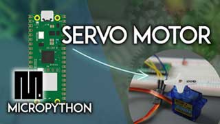
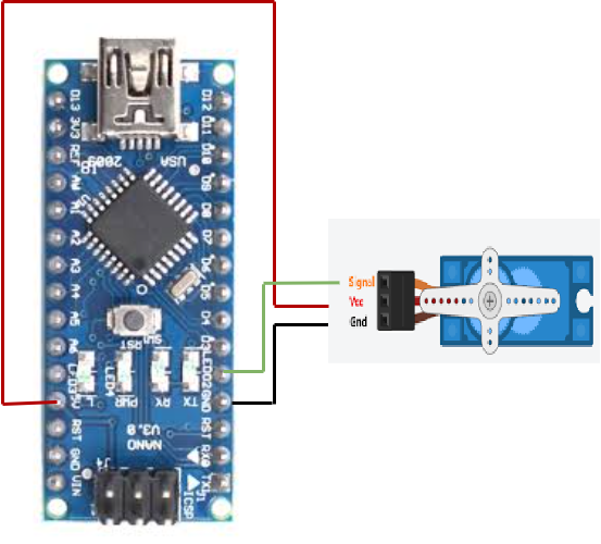
Design and implement a system with an Arduino Nano to control a servo motor, rotating to specific angles like 90 or 180 degrees based on user input or sensor data.
#include <Servo.h>
Servo servo_pin_2;
void setup(){
servo_pin_2.attach(2,530,2600);
}
void loop(){
servo_pin_2.write( 0 );
delay( 2000 );
servo_pin_2.write( 90 );
delay( 2000 );
servo_pin_2.write( 0 );
delay( 2000 );
servo_pin_2.write( 90 );
delay( 1000 );
}
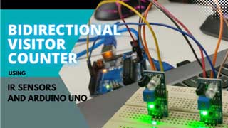
To detect and respond to the presence or movement of objects using infrared light.
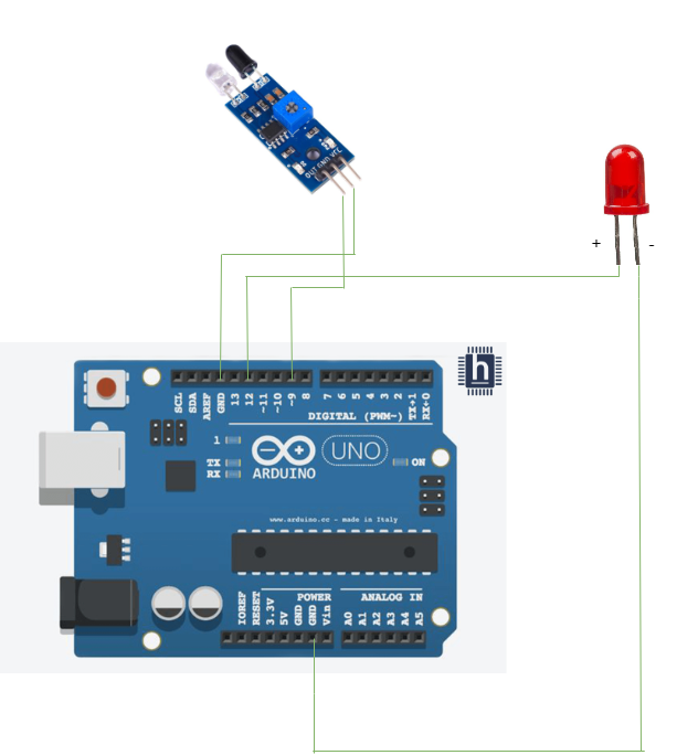
int IRSensor = 9; // connect ir sensor module to Arduino pin 9
int LED = 12; // conect LED to Arduino pin 13
void setup(){
Serial.begin(115200); // Init Serila at 115200 Baud
Serial.println("Serial Working"); // Test to check if serial is working or not
pinMode(IRSensor, INPUT); // IR Sensor pin INPUT
pinMode(LED, OUTPUT); // LED Pin Output
}
void loop(){
int sensorStatus = digitalRead(IRSensor); // Set the GPIO as Input
if (sensorStatus == 1) // Check if the pin high or not
{ // if the pin is high turn off the onboard Led
digitalWrite(LED, HIGH); // LED LOW
Serial.println("Motion Ended!"); // print Motion Detected! on the serial
monitor window
}
else {
//else turn on the onboard LED
digitalWrite(LED, LOW); // LED High
Serial.println("Motion Detected!"); // print Motion Ended! on the serial
monitor window
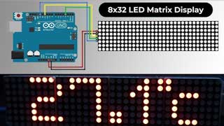
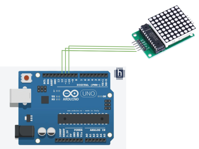
} }The objective of using a dot matrix display with Arduino is to display text, symbols, and images.
//////////////////////////////////
//  LED Matrix MAX7219 Tutorial //
//          ArduinoCraft        //
//////////////////////////////////
// connect the necessary library
#include "LedControl.h"
// jumper pin settings
#define DIN 10
#define CS 11
#define CLK 12
// this variable indicates the number of matrices, counting starts from zero
#define myMat 0
// initialization of LED matrix from library
LedControl ledMat = LedControl(DIN, CLK, CS, myMat);
// variable of array type, 1 indicates lit LEDs
byte charH[8] = {
  B00100010,
  B00100010,
  B00111110,
  B00100010,
  B00100010,
  B00100010,
  B00100010,
  B00000000
};
byte charE[8] = {
  B01111100,
  B01000000,
  B01000000,
  B01110000,
  B01000000,
  B01000000,
  B01111100,
  B00000000
};
byte charL[8] = {
  B01000000,
  B01000000,
  B01000000,
  B01000000,
  B01000000,
  B01000000,
  B01111100,
  B00000000
};
byte charO[8] = {
  B00011100,
  B00100010,
  B01000001,
  B01000001,
  B01000001,
  B01000001,
  B00100010,
  B00011100
};

void setup() {
  // wake up the matrix to start communication
  ledMat.shutdown(myMat, false);
  // setting the LED matrix to medium brightness (0-15)
  ledMat.setIntensity(myMat, 7);
  // switching off all LEDs on the matrix
  ledMat.clearDisplay(myMat);
}

void loop() {
  // drawing a character from a variable
  // H
  for (int i = 0; i < 8; i++) {
    ledMat.setRow(myMat, i, charH[i]);
  }
  delay(1000);                 // delay 1000 ms
  ledMat.clearDisplay(myMat);  // clear display
  // E
  for (int i = 0; i < 8; i++) {
    ledMat.setRow(myMat, i, charE[i]);
  }
  delay(1000);
  ledMat.clearDisplay(myMat);
  // L
  for (int i = 0; i < 8; i++) {
    ledMat.setRow(myMat, i, charL[i]);
  }
  delay(1000);
  ledMat.clearDisplay(myMat);
  // L
  for (int i = 0; i < 8; i++) {
    ledMat.setRow(myMat, i, charL[i]);
  }
  delay(1000);
  ledMat.clearDisplay(myMat);
  // O
  for (int i = 0; i < 8; i++) {
    ledMat.setRow(myMat, i, charO[i]);
   }
  delay(1000);
  ledMat.clearDisplay(myMat);

  // rendering of LEDs in the given row, here the fourth row
  // (rows are numbered from 0 to 7)
  ledMat.setRow(myMat, 3, B10101010);
  delay(1000);
  // rendering of LEDs in a given column, here the sixth column
  // (columns are numbered from 0 to 7)
  ledMat.setColumn(myMat, 5, B10111010);
  delay(1000);
  // rendering of one selected LED, here the outermost LED [8,8]
  ledMat.setLed(myMat, 7, 7, true);
  delay(1000);
  // demonstration of light intensity change in the whole range 0 to 15
  for (int i = 0; i < 16; i++) {
    ledMat.setIntensity(myMat, i);
    delay(200);
  }
  ledMat.setIntensity(myMat, 7);
  ledMat.clearDisplay(myMat);
}
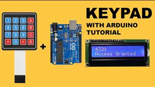
To show the pressing number of the keyboard on the LCD display.
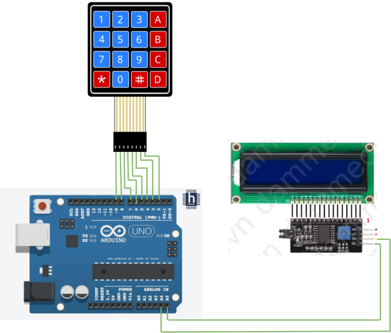
#include <Keypad.h>
#include <Wire.h>
#include <LiquidCrystal_I2C.h>
const byte ROWS = 4;
const byte COLS = 4;
char hexaKeys[ROWS][COLS] = {
{'1', '2', '3', 'A'}, {'4', '5', '6', 'B'}, {'7', '8', '9', 'C'}, {'*', '0', '#', 'D'}};
byte rowPins[ROWS] = {9, 8, 7, 6};
byte colPins[COLS] = {5, 4, 3, 2};
Keypad customKeypad = Keypad(makeKeymap(hexaKeys), rowPins,
colPins, ROWS, COLS);
LiquidCrystal_I2C lcd(0x27, 16, 2);
void setup(){
// Serial.begin(9600);
lcd.backlight();
lcd.init();
lcd.clear();}
void loop(){
char customKey = customKeypad.getKey();
if (customKey){
lcd.setCursor(0, 0);
lcd.print(customKey);
// Serial.print(customKey);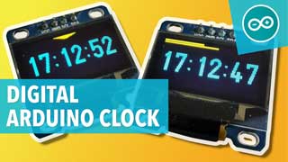
}}To initialize the RTC module, display time and date on an LCD, and update the clock every second.
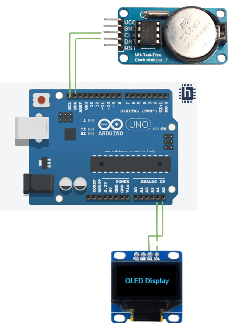
#include <Wire.h>
#include <Adafruit_SSD1306.h>
#include "RTClib.h"
//#include "DS1307RTC.h"
#define SCREEN_WIDTH 128 // OLED display width, in pixels
#define SCREEN_HEIGHT 64 // OLED display height, in pixels
RTC_DS1307 rtc;

char daysOfTheWeek[7][12] = {"Sunday", "Monday", "Tuesday", "Wednesday", "Thursday", "Friday", "Saturday"};

// Declaration for an SSD1306 display connected to I2C (SDA, SCL pins)
Adafruit_SSD1306 display(SCREEN_WIDTH, SCREEN_HEIGHT, &Wire, -1);
void setup ()
{
  Serial.begin(9600);
  delay(3000); // wait for console opening

 if(!display.begin(SSD1306_SWITCHCAPVCC, 0x3C)) { // Address 0x3D for 128x64
    Serial.println(F("SSD1306 allocation failed"));
    for(;;);
  }
  if (! rtc.begin()) {
    Serial.println("Couldn't find RTC");
    while (1);
  }

  // if (rtc.lostPower()) {
  //   Serial.println("RTC lost power, lets set the time!");

  // Comment out below lines once you set the date & time.
    // Following line sets the RTC to the date & time this sketch was compiled
   rtc.adjust(DateTime(F(__DATE__), F(__TIME__)));
    //rtc.adjust(DateTime(2024, 06, 15, 04, 35, 20));
    // Following line sets the RTC with an explicit date & time
    // for example to set January 27 2017 at 12:56 you would call:
    // rtc.adjust(DateTime(2017, 1, 27, 12, 56, 0));
  //}

   display.display();
 delay(2);
 display.clearDisplay();


display.clearDisplay();
display.setTextColor(WHITE);
//display.startscrollright(0x00, 0x0F);
display.setTextSize(2);
display.setCursor(0,5);
display.print("  Clock ");
display.display();
delay(3000);
}

void loop ()
{
    DateTime now = rtc.now();

    Serial.println("Current Date & Time: ");
    Serial.print(now.year(), DEC);
    Serial.print('/');
    Serial.print(now.month(), DEC);
    Serial.print('/');
    Serial.print(now.day(), DEC);
    Serial.print(" (");
    Serial.print(daysOfTheWeek[now.dayOfTheWeek()]);
    Serial.print(") ");
    Serial.print(now.hour(), DEC);
    Serial.print(':');
    Serial.print(now.minute(), DEC);
    Serial.print(':');
    Serial.print(now.second(), DEC);
    Serial.println();

    display.clearDisplay();
    display.setTextSize(2);
    display.setCursor(75,0);
    display.println(now.second(), DEC);
    display.setTextSize(2);
    display.setCursor(25,0);
    display.println(":");

    display.setTextSize(2);
    display.setCursor(65,0);
    display.println(":");

    display.setTextSize(2);
    display.setCursor(40,0);
    display.println(now.minute(), DEC);

    display.setTextSize(2);
    display.setCursor(0,0);
    display.println(now.hour(), DEC);

    display.setTextSize(2);
    display.setCursor(0,20);
    display.println(now.day(), DEC);

    display.setTextSize(2);
    display.setCursor(25,20);
    display.println("/");

    display.setTextSize(2);
    display.setCursor(40,20);
    display.println(now.month(), DEC);

    display.setTextSize(2);
    display.setCursor(55,20);
    display.println("/");

    display.setTextSize(2);
    display.setCursor(70,20);
    display.println(now.year(), DEC);

    display.setTextSize(2);
    display.setCursor(0,40);
    display.print(daysOfTheWeek[now.dayOfTheWeek()]);

    display.display();

    Serial.println();
    delay(1000);
}
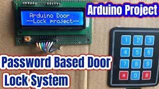
To make a password checker using keypad, LCD, and relay
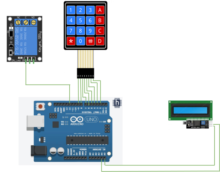
#include <Wire.h>
#include <LiquidCrystal_I2C.h>
#include <Keypad.h>

#define Password_Length 8

int signalPin = 12;

char Data[Password_Length];
char Master[Password_Length] = "12A457B";
byte data_count = 0, master_count = 0;
bool Pass_is_good;
char customKey;

const byte ROWS = 4;
const byte COLS = 4;

char hexaKeys[ROWS][COLS] = {
  {'1', '2', '3', 'A'},
  {'4', '5', '6', 'B'},
  {'7', '8', '9', 'C'},
  {'*', '0', '#', 'D'}
};

byte rowPins[ROWS] = {9, 8, 7, 6};
byte colPins[COLS] = {5, 4, 3, 2};

Keypad customKeypad = Keypad(makeKeymap(hexaKeys), rowPins, colPins, ROWS, COLS);

LiquidCrystal_I2C lcd(0x27, 16, 2);

void setup(){
  lcd.init();
  lcd.backlight();
  pinMode(signalPin, OUTPUT);
}

void loop(){

  lcd.setCursor(0,0);
  lcd.print("Enter Password:");

  customKey = customKeypad.getKey();
  if (customKey){
    Data[data_count] = customKey;
    lcd.setCursor(data_count,1);
    lcd.print(Data[data_count]);
    data_count++;
    }

  if(data_count == Password_Length-1){
    lcd.clear();

    if(!strcmp(Data, Master)){
      lcd.print("Correct");
      digitalWrite(signalPin, HIGH);
      delay(5000);
      digitalWrite(signalPin, LOW);
      }
    else{
      lcd.print("Incorrect");
      delay(1000);
      }

    lcd.clear();
    clearData();
  }
}

void clearData(){
  while(data_count !=0){
    Data[data_count--] = 0;
  }
  return;
}
The Display shows the user’s input and Status messages as listed below:
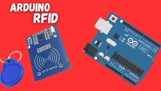
Learn how RFID receiver works and how to reading access cards
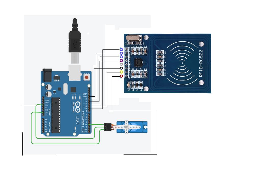
#include <SPI.h>
#include <MFRC522.h>
#include <Servo.h>
#define SS_PIN 10
#define RST_PIN 9
MFRC522 mfrc522(SS_PIN, RST_PIN); // Create MFRC522 instance.
#define servoPin 3
Servo myServo;
int pos = 0;
void setup() {
Serial.begin(9600); // Initiate a serial communication
SPI.begin(); // Initiate SPI bus
mfrc522.PCD_Init(); // Initiate MFRC522
Serial.println("Approximate your card to the reader...");
Serial.println();
myservo.attach(3); }
void loop() {
// Look for new cards
if ( ! mfrc522.PICC_IsNewCardPresent()) {
return; }
// Select one of the cards
if ( ! mfrc522.PICC_ReadCardSerial()) {
return; }
//Show UID on serial monitor
Serial.print("UID tag :");
String content= "";
byte letter;
for (byte i = 0; i < mfrc522.uid.size; i++) {
Serial.print(mfrc522.uid.uidByte[i] < 0x10 ? " 0" : " ");
Serial.print(mfrc522.uid.uidByte[i], HEX);
content.concat(String(mfrc522.uid.uidByte[i] < 0x10 ? " 0" : " "));
content.concat(String(mfrc522.uid.uidByte[i], HEX)); }
Serial.println();
Serial.print("Message : ");
content.toUpperCase();
if (content.substring(1) == "XXXXXXXX") //change here the UID of the
card/cards that you want to give access
{
Serial.println("Authorized access");
Serial.println();
sweepServo();
delay(3000); }
else {
Serial.println(" Access denied");
delay(3000);
} }
void sweepServo(){
for (pos = 0; pos <= 180; pos += 1) { // goes from 0 to 180 degrees
// in steps of 1 degree
myservo.write(pos); // tell servo to go to position in variable 'pos'
delay(15); // waits 15ms for the servo to reach the position
}
for (pos = 180; pos >= 0; pos -= 1) { // goes from 180 degrees to 0
degrees
myservo.write(pos); // tell servo to go to position in variable 'pos'
delay(15); // waits 15ms for the servo to reach the position
}}
An RFID reader scans a tag, and based on its authorization, the servo motor rotates to open the door .
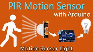
Sensing the object movements and learn how PIR Sensor works.
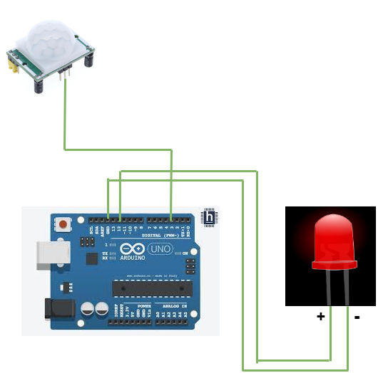
int led = 12; // the pin that the LED is atteched to
int sensor = 3; // the pin that the sensor is atteched to
int state = LOW; // by default, no motion detected
int val = 0; // variable to store the sensor status (value)
void setup() {
pinMode(led, OUTPUT); // initalize LED as an output
digitalWrite(led, LOW);
pinMode(sensor, INPUT); // initialize sensor as an input
Serial.begin(9600); // initialize serial
}
void loop(){
delayMicroseconds(250);
val = digitalRead(sensor); // read sensor value
if (val == LOW) { // check if the sensor is HIGH
digitalWrite(led, LOW); // turn LED ON
delay(100); // delay 100 milliseconds
if (state == HIGH) {
Serial.println("Motion detected!");
state = HIGH; // update variable state to HIGH
//delayMicroseconds(200);
}
}
else {
digitalWrite(led, HIGH); // turn LED OFF
delay(100); // delay 200 milliseconds
if (state == HIGH){
Serial.println("Motion stopped!");
state = LOW; // update variable state to LOW
} }}Sensing the distance of objects and learn how Ultrasonic Sensor works
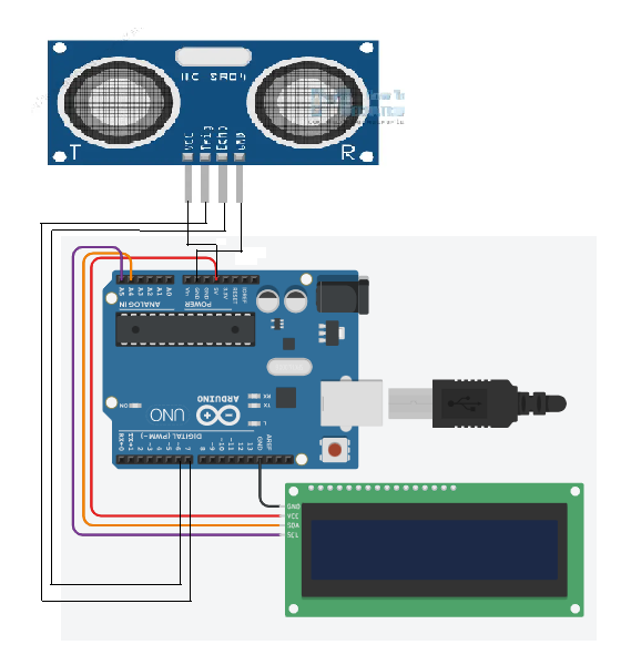
#include <Wire.h>
#include <LiquidCrystal_I2C.h>
LiquidCrystal_I2C lcd(0x27, 16, 2);
#define trigPin 6
//Sensor Echo pin connected to Arduino pin 13
#define echoPin 7
//Sensor Trip pin connected to Arduino pin 12
void setup(){
pinMode(trigPin, OUTPUT);
pinMode(echoPin, INPUT);
lcd.init();
lcd.backlight();
// lcd.clear();
lcd.setCursor(4,0);
lcd.print("Blue Nile");
lcd.setCursor(4,1);
lcd.print("Software");
//lcd.print("Moving Text!!!");
delay(2000);
lcd.clear();
lcd.setCursor(0,0);
//Set LCD cursor to upper left corner, col 0, row 0
lcd.print("Target Distance:");
//Print Message on First Row
//lcd.print("");
delay(2000);
}
void loop(){
long duration, distance;
digitalWrite(trigPin, LOW);
delayMicroseconds(2);
digitalWrite(trigPin, HIGH);
delayMicroseconds(5);
digitalWrite(trigPin, LOW);
duration = pulseIn(echoPin, HIGH);
distance = (duration/2) / 29.1;
lcd.setCursor(0,1); //Set cursor to 1st col of 2nd row
lcd.print(" "); //Print blanks to clear the row
lcd.setCursor(0,1); //Set Cursor again to 1st col of 2nd row
lcd.print(distance); //Print measured distance
lcd.print(" cm"); //Print your units.
delay(250); //pause to let things settle
}Sensing the light intensity and learn how LDR Sensor works
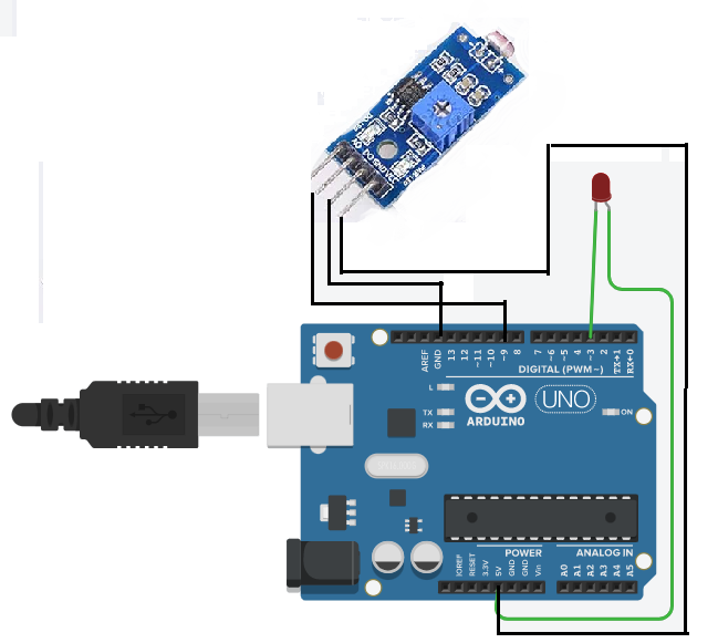
int LEDPin = 3;
int LDRPin = 9;
int HIGH2 = 0;
int LOW2 = 1;
void setup(){
pinMode(LEDPin, OUTPUT);
digitalWrite(LEDPin, LOW2);
pinMode(LDRPin, INPUT_PULLUP); }
void loop(){
int detection = !digitalRead(LDRPin);
if (detection == HIGH2){
digitalWrite(LEDPin , HIGH2);
}
if (detection == LOW2){
digitalWrite(LEDPin , LOW2);
} }Blue Nile Software Systems Private Ltd is a professional IT Company supported by DMI Foundations,servicing the society for the past 18 years, it was incorporated on 26 August 2005.
Copyright © All rights reserved | Design & Developed by Blue Nile Software Systems Pvt. Ltd