OBJECTIVE
The objective of using a dot matrix display with Arduino is to display text, symbols, and images.
MODULES REQUIRED
- Arduino UNO
- 8x8 LED matrix
- Jumper wire
SCHEMATIC DIAGRAM
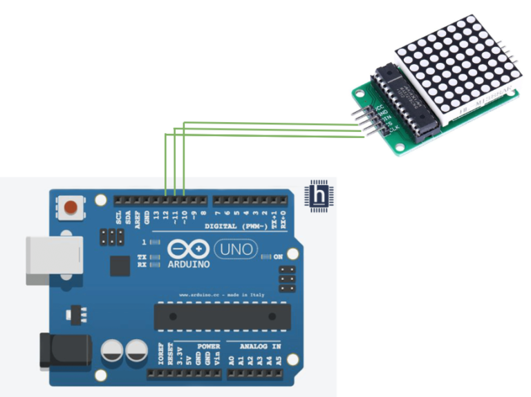
Connect Dot matrix:
- Connect the Din pin on the Dot matrix to Arduino pin D10
- Connect the Cs pin on the Dot matrix to Arduino Pin D11
- Connect the Clk pin on the Dot matrix to Arduino Pin D12
ARDUINO CODE
ARDUINO CODE
C++
//////////////////////////////////
//  LED Matrix MAX7219 Tutorial //
//          ArduinoCraft        //
//////////////////////////////////
// connect the necessary library
#include "LedControl.h"
// jumper pin settings
#define DIN 10
#define CS 11
#define CLK 12
// this variable indicates the number of matrices, counting starts from zero
#define myMat 0
// initialization of LED matrix from library
LedControl ledMat = LedControl(DIN, CLK, CS, myMat);
// variable of array type, 1 indicates lit LEDs
byte charH[8] = {
  B00100010,
  B00100010,
  B00111110,
  B00100010,
  B00100010,
  B00100010,
  B00100010,
  B00000000
};
byte charE[8] = {
  B01111100,
  B01000000,
  B01000000,
  B01110000,
  B01000000,
  B01000000,
  B01111100,
  B00000000
};
byte charL[8] = {
  B01000000,
  B01000000,
  B01000000,
  B01000000,
  B01000000,
  B01000000,
  B01111100,
  B00000000
};
byte charO[8] = {
  B00011100,
  B00100010,
  B01000001,
  B01000001,
  B01000001,
  B01000001,
  B00100010,
  B00011100
};

void setup() {
  // wake up the matrix to start communication
  ledMat.shutdown(myMat, false);
  // setting the LED matrix to medium brightness (0-15)
  ledMat.setIntensity(myMat, 7);
  // switching off all LEDs on the matrix
  ledMat.clearDisplay(myMat);
}

void loop() {
  // drawing a character from a variable
  // H
  for (int i = 0; i < 8; i++) {
    ledMat.setRow(myMat, i, charH[i]);
  }
  delay(1000);                 // delay 1000 ms
  ledMat.clearDisplay(myMat);  // clear display
  // E
  for (int i = 0; i < 8; i++) {
    ledMat.setRow(myMat, i, charE[i]);
  }
  delay(1000);
  ledMat.clearDisplay(myMat);
  // L
  for (int i = 0; i < 8; i++) {
    ledMat.setRow(myMat, i, charL[i]);
  }
  delay(1000);
  ledMat.clearDisplay(myMat);
  // L
  for (int i = 0; i < 8; i++) {
    ledMat.setRow(myMat, i, charL[i]);
  }
  delay(1000);
  ledMat.clearDisplay(myMat);
  // O
  for (int i = 0; i < 8; i++) {
    ledMat.setRow(myMat, i, charO[i]);
   }
  delay(1000);
  ledMat.clearDisplay(myMat);

  // rendering of LEDs in the given row, here the fourth row
  // (rows are numbered from 0 to 7)
  ledMat.setRow(myMat, 3, B10101010);
  delay(1000);
  // rendering of LEDs in a given column, here the sixth column
  // (columns are numbered from 0 to 7)
  ledMat.setColumn(myMat, 5, B10111010);
  delay(1000);
  // rendering of one selected LED, here the outermost LED [8,8]
  ledMat.setLed(myMat, 7, 7, true);
  delay(1000);
  // demonstration of light intensity change in the whole range 0 to 15
  for (int i = 0; i < 16; i++) {
    ledMat.setIntensity(myMat, i);
    delay(200);
  }
  ledMat.setIntensity(myMat, 7);
  ledMat.clearDisplay(myMat);
}
INSTRUCTIONS
- Connect the modules and components as per the schematic diagram.
- Download and install Ledcontrol.
- Upload the Arduino code into the Arduino board.
- To check the dot matrix display, it shows the "HELLO" words.
WORKING
- A dot matrix display using Arduino works by controlling individual LEDs in a grid via rows and columns, typically using shift registers to manage the data, allowing characters or patterns to be displayed.