OBJECTIVE
The objective is to learn how to control high-power devices using a relay by sending a digital signal from a microcontroller. This involves using a relay module to safely switch high-power devices on and off with low-voltage control signals.
MODULES REQUIRED
- LED
- Jumper Wires
- Relay
- Arduino uno
SCHEMATIC DIAGRAM
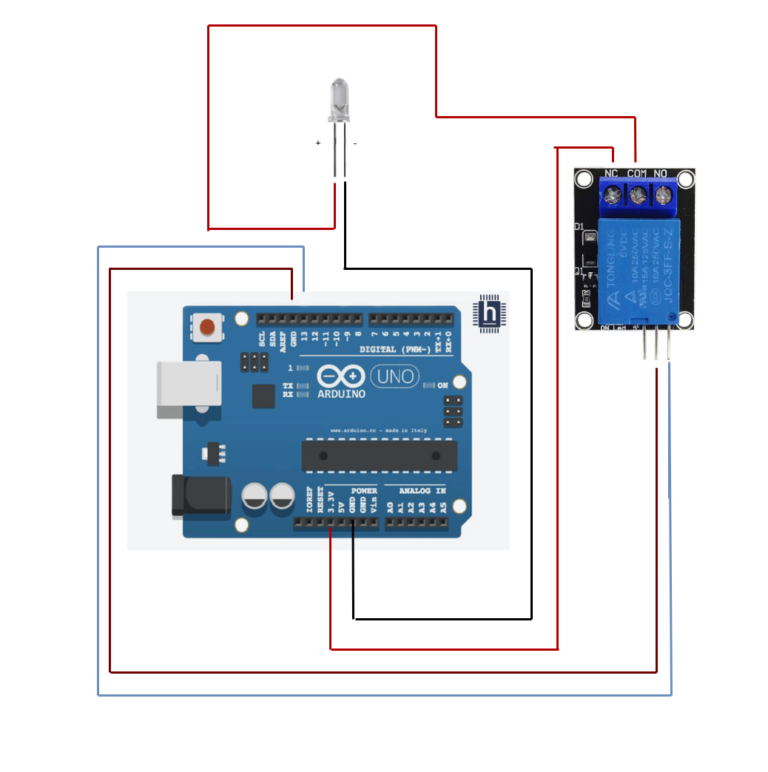
- Connect the Relay module Pin and Gnd to Arduino pins D13 and GND.
- Connect the Arduino 3.3v to relay pin NC (Normally closed)
- Connect the led positive to Relay pin COM.
- Connect the LED negative to Arduino pin GND
ARDUINO CODE
JavaScript
int relay = 13; // Plug the relay into Digital Pin 13


void setup() {
  pinMode(relay, OUTPUT);
}


void loop() {
  digitalWrite(relay, HIGH); // Turn the relay on
  delay(1000); // Wait 1 second
  digitalWrite(relay, LOW); // Turn the relay Off
  delay(1000); // Wait 1 second
}
INSTRUCTIONS
- Connect the modules & components as per schematic diagram.
- Upload the Arduino code into Arduino board
- Verify the relay switch. POWERS UP THE LED In accordance with the code, the normal LED turns off.
WORKING
- When the signal gets from Arduino uno the relay switch is ON and the Normal LED Gets OFF and vice versa.