OBJECTIVE
Understand the functions of Push buttons and LEDs, and control LEDs using Arduino platform.
MODULES REQUIRED
- Arduino Board
- 1 x LED
- 1 x 1k Resistor
- Jumper wires
- Push button
SCHEMATIC DIAGRAM
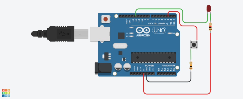
- Connect LED’s pin (anode) to D12 (output)
- Connect Push button pin to D2 (Input)
Following connection are made in inbuilt circuit, so there no need made these connection:
- LED’s anode connected to 5V using a 1K pull-up resistor
- Push button pulled down to GND using 10K pull-down resistor
ARDUINO CODE
JavaScript
int LOW2=1;
int HIGH2=0;
void setup(){
pinMode(12, OUTPUT);
digitalWrite(12, LOW2);
pinMode(2,INPUT_PULLUP);
Serial.begin(9600);
}
void loop(){
int button = digitalRead(2);
delay(10);
Serial.print(button);
if (button){
digitalWrite(12, HIGH2);
delay(1000); // Wait for 1000 millisecond(s)
digitalWrite(12, LOW2);
delay(500); // Wait for 1000 millisecond(s)
}}INSTRUCTIONS
- Connect the modules & components as per schematic diagram.
- Upload the Arduino code into Arduino board.
- Verify the LED on and off with push button presses.
WORKING
- When the button is pressed, pin 12 is 5V (HIGH).
- When the button is released, pin 12 is 0V (LOW).
- So we will see the LED light up and go out alternately as the button is pressed and released.